
I have been asked many times how I go about this, so I figured it would be worthwhile to lay it out so I can just disseminate a link. I have better things to do than repeat myself all the time. Why do you want to bother? The first of the RX-7 lineup is a cheap (used to be), simple car but one of the biggest drawbacks is everything forward of the firewall. Yes, I am going include the 12a in that statement because Mazda has deemed many parts to be NLA and now they are a novelty more than anything. However, we can solve this and make these little cars a bit more modern and a lot more fun to drive.
I want to be clear that I am not the first person to do this, nor do I know who was. What I do know is a good friend of mine did this around 2006 to solve many of the inequities of the first gen chassis and I was amazed at the simplicity of it. As it turns out, Mazda developed the FC suspension on the FB to keep prying eyes from knowing too much about the redesign. This has led to the rather fortunate fact that the front subframe from the FC is dimensionally compatible with the FB. So much so, that in one method you can reuse two of the FB’s original studs to mount and located the FC subframe. Pretty damn nifty.
The nomenclature (so we are all on the same page)
- FC – referring to the 1986-1991 model years of Rx-7 and the source of the parts to be installed, source from the vin stamping.
- FB – Technically the 1981-1985 model years in the US, however “SA” used in other markets and for 79-80 in US.
What do you need?
- Misc. Metric tools
- From the FC: subframe, steering rack, hubs, knuckles, brakes, steering column from FC or powersteering FB, coilovers. I say coilovers because cobbled together FC/FB dampers and springs nearly hit the wheel and the stock upper mounts wont allow for cambering (nearly positive camber with stock).
- A rear, lower suspension link from the FB
- High grade, long metric bolts (length determined later)
- Hammer
- Round file
- Jack and stands
- Angle grinder
- Drill
- A welder, 110v MIG will do fine.
- Gin
How do you begin?
- Simply put, remove everything. The engine, the subframe, the suspension, brakes, steering box, the lot of it. You will find that the steering box for the non power steering cars is a bit feisty to get since it directly enters the box. This requires a straight removal and is evidence that I wasn’t bullshitting you about needing the power steering column OR an FC column. Outside of this you can always make a custom thing, but I leave that to your imagination.
- Remember those choose your own ending books when you were little? This is a bit like that. You need to decide if you are going to use the original front studs to locate the subframe, or do it yourself. The trade off is simple. Locating with the original studs moves the subframe forward one inch, which causes the tires to interfere with the fender. This means trimming the fender or flares. That said, this route is very easy, and you gain an inch of wheelbase, and some castor. Finally, if you use the stock engine mount arrangement, the water pump comes in close contact with the FB radiator, making a cooling fan setup very difficult. Given all that, this is what I have done on most of my swaps. Otherwise, you must located the subframe yourself, being very careful to locate the axle in the center of the fenders and but be sure to make it square. Friends have done this with success, but obviously requires more attention to detail.
Let’s assume you want to do what I did…
- With a cleared engine bay, hop in and remove the rear studs by grinding away the welds. With ample grindage, you can pop them out by hitting from below with a hammer.
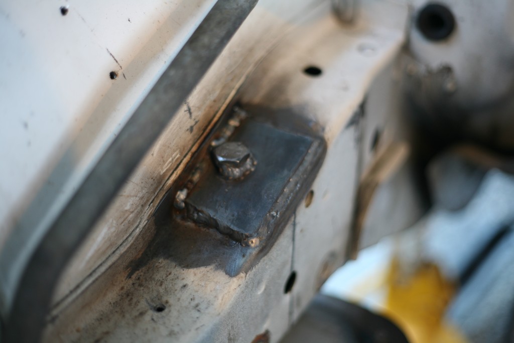
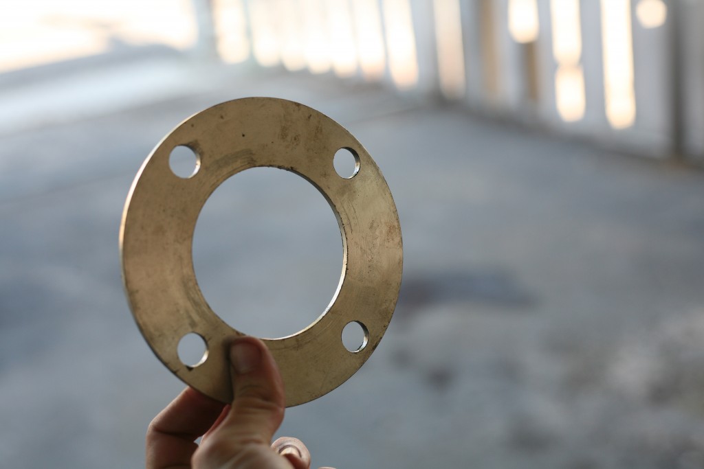
- Since the bolts that you can buy readily have smaller heads, I make a support plate from 1/8″ steel, typically 2″ wide stock cut down to size. I then drill and file a whole for the bolt to pass through that allows the bolt to be upright and the plate to meet the angle of the body. (see image below)
- Its best to measure for the next step, which is getting the right bolt for the rear. I was able to source high grade, metric bolts from my local Fastenal. Your results may vary. They need to be long enough that the threads poke through the bottom to allow the bolt to thread fully. Since I used the supporting spacer, some length is added there. I forgot what I used at the time, but since bolts only coming in varying lengths, its pretty obvious which will work for you.
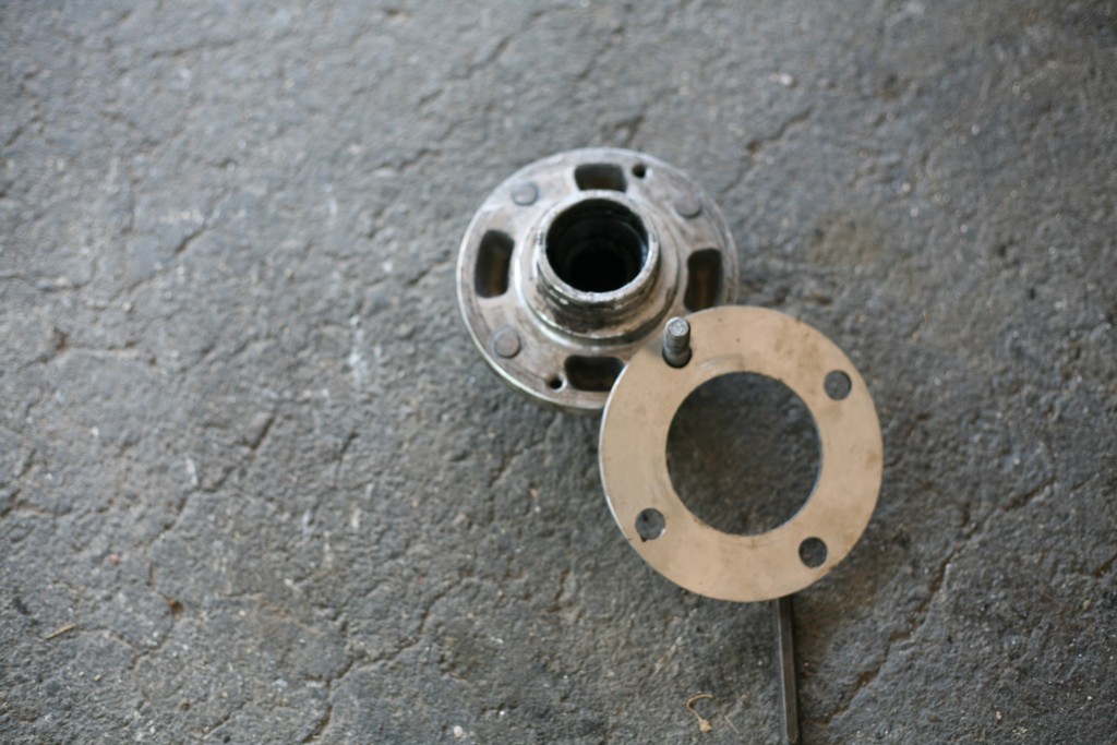
- On the subframe, grind off the locator studs that stick up. They will prevent you from mounting flush to the frame. If your OCD, then your welcome to locate and drill holes in the body for them as opposed to removal.
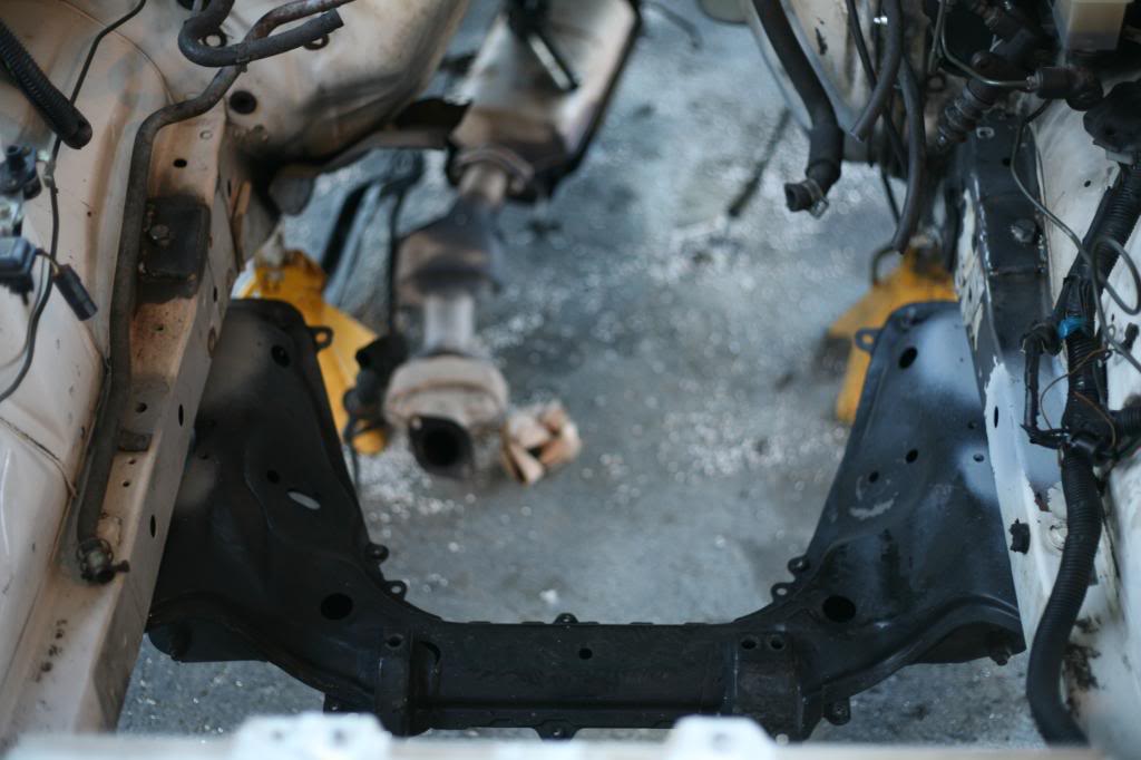
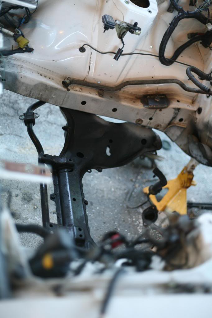
- Loosely attach the subframe. You should notice that the crimp of the body sheet metal hits the subframe. Mark and trim these spots. Be careful not to cut through the body! (see image below)
- Once its all assembled and torqued, you can now weld the head of the bolt to the plate. (see image below)
Now you can begin putting things back in!
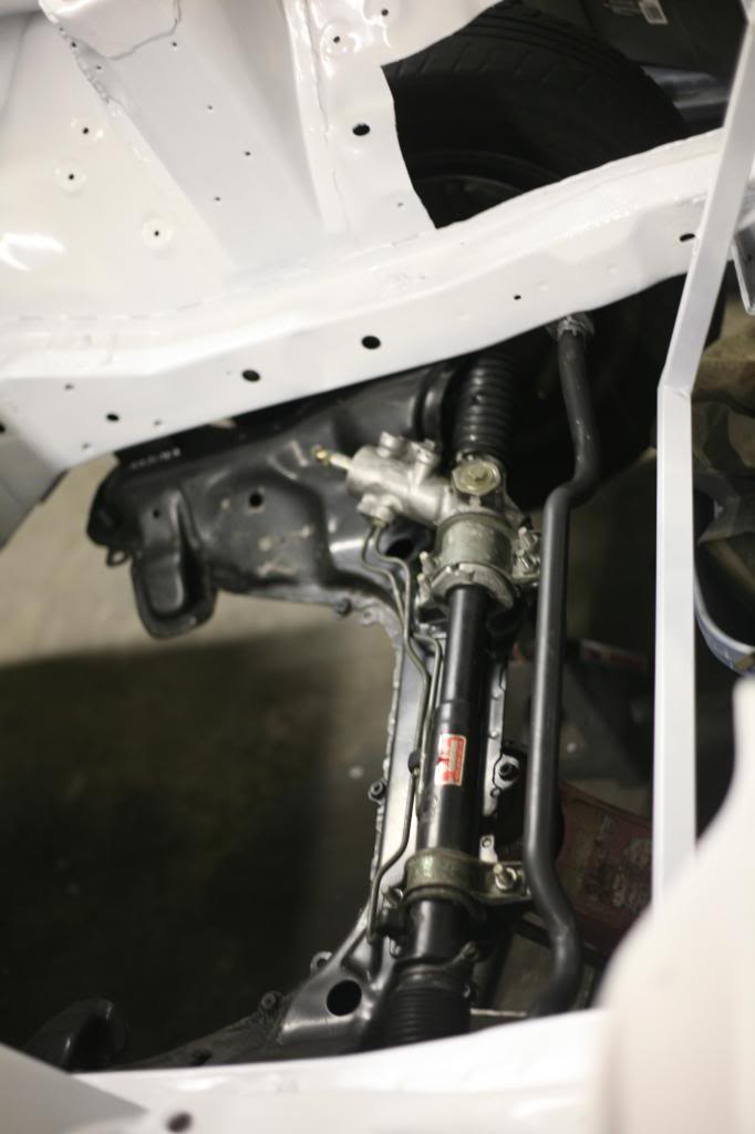
- You can stick in the rack and pinion. Both the power steering or non-power steering variants work. This is a good time for replacing boots, seals, rod ends, etc. Also, the “proper manual conversion” is great for those who do not like their steering assisted.
- If you wish to have the sway bar, now is the time to located it. You will need to weld in threaded bungs. Also ensure that the movement of the suspension is good at the location before you weld.
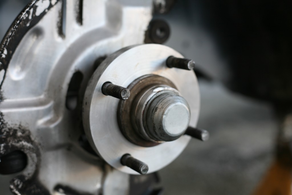
- The hubs and knuckles should attach as OEM intended. Sometimes junkyard items are damaged. You’ll find out at this step.
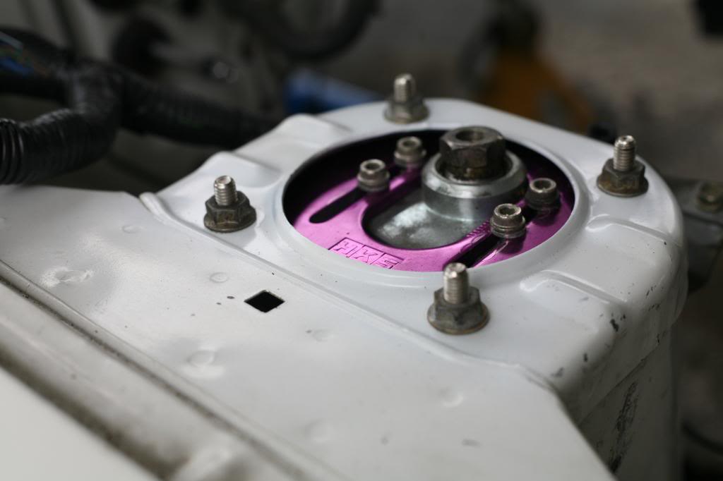
- Coilovers……almost! Now you must use FB pillow ball mounts, or break out the round file. You will notice that the FB four hole distance is smaller than the FC. A company called T3 makes an FC – FB intercompatible pillow ball, however, they are rather puny in both the bearing size and plate design. They work okay but I’m not impressed by them. If you compare them to the HKS pillow balls, you will see the difference. I resolved this by carefully round filing the holes directly outward until reaching the FC spacing. Mark carefully and take your time.
- Now you can add the coilovers.
You are not done yet. You need to connect the steering column. So once again you have to make some choices:
- The FB power steering column will bolt into the underdash and accept the various controls with ease.
- The FC column requires removal of brackets and attachment of FB column mounts. The FC column is also not going to mount the FB switches. They have difference diameters for mounting.
- You can make something custom.
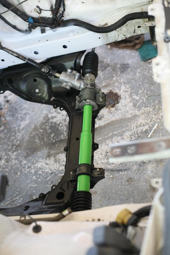
Regardless, you need to lengthen the FC intermediate shaft to meet with the steering column. This is done by cutting in half, then elongating with a metal tube. As it happens, the rear suspension link inner diameter is the same as the steering shaft’s outer diameter! Before welding together, ensure that the u-joints are positioned in phase otherwise you will get an elliptical motion in the intermediate shaft making for unusual steering feel. There is room for interpretation here and likely more ways than I’ve considered. As such, be prepared for some tomfoolery to get this step done, especially without the power steering column.
What about using 4 lug hubs on the 4 piston brakes?
- A long time ago, on a well known rotary car forum, a thread was made about how to do this. Googling the topic should bring up the how to. Essentially;
- make two, 4mm spacers.
- Redrill the rotors to 4×114.3.
- Assemble.
- This is actually harder than I made it sound if your tooling is crude.
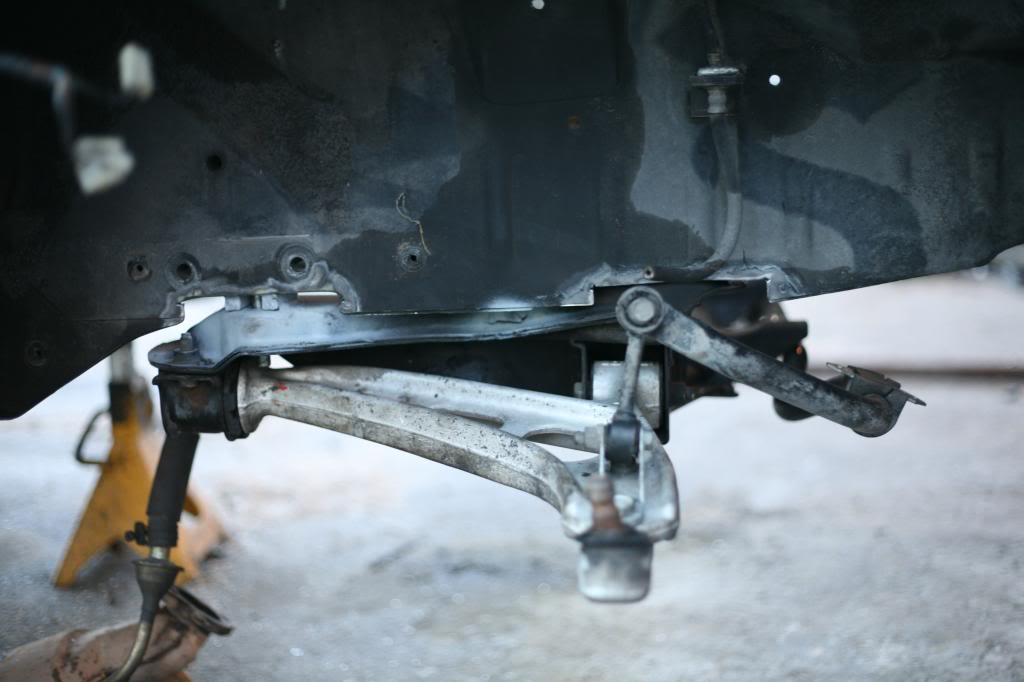
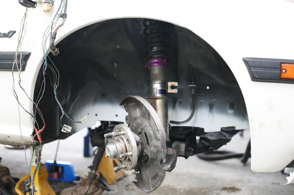
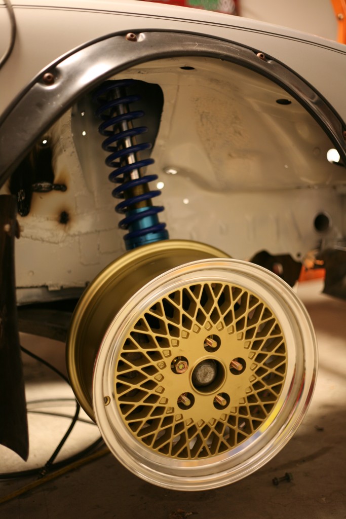
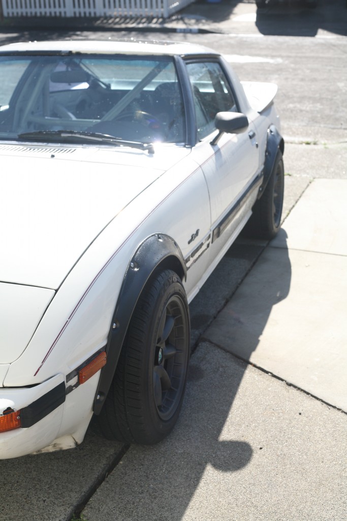
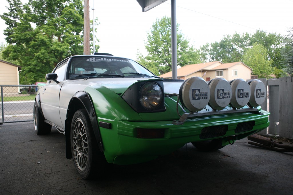
The finished product!
- Being that I trimmed the fenders, I opted for flares from 240z.
- The steering is quicker, with greatly improved feedback.
- Handing is superb.
- Brakes are improved.
- Everything is serviceable.


